how dC motor works?
DC motor definition:
A DC motor is any of a class of rotary electrical machines that converts direct current electrical power into mechanical power. The most common types rely on the forces produced by magnetic fields.
Working Principle Of A DC Motor
A motor is an electrical machine which converts electrical energy into mechanical energy. The principle of working of a DC motor is that "whenever a current carrying conductor is placed in a magnetic field, it experiences a mechanical force". The direction of this force is given by Fleming's left hand rule and it's magnitude is given by F = BIL. Where, B = magnetic flux density, I = current and L = length of the conductor within the magnetic field.
Fleming's left hand rule: If we stretch the first finger, second finger and thumb of our left hand to be perpendicular to each other AND direction of magnetic field is represented by the first finger, direction of the current is represented by second finger then the thumb represents the direction of the force experienced by the current carrying conductor.
_50_degree_split_ring.gif "working of dc motor animation") |
| Animation: Working of DC Motor |
Working animation of DC motor
Above animation helps in understanding the working principle of a DC motor. When armature windingsare connected to a DC supply, current sets up in the winding. Magnetic field may be provided by field winding (electromagnetism) or by using permanent magnets. In this case, current carrying armature conductors experience force due to the magnetic field, according to the principle stated above.
Commutator is made segmented to achieve unidirectional torque. Otherwise, the direction of force would have reversed every time when the direction of movement of conductor is reversed the magnetic field.
This is how a DC motor works!Back EMF
According to fundamental laws of nature, no energy conversion is possible until there is something to oppose the conversion. In case of generators this opposition is provided by magnetic drag, but in case of dc motors there is back emf.
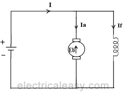
When the armature of the motor is rotating, the conductors are also cutting the magnetic flux lines and hence according to the Faraday's law of electromagnetic induction, an emf induces in the armature conductors. The direction of this induced emf is such that it opposes the armature current (Ia) . The circuit diagram below illustrates the direction of the back emf and armature current. Magnitude of Back emf can be given by the emf equation of DC generator.
Significance Of Back Emf:
Magnitude of back emf is directly proportional to speed of the motor. Consider the load on a dc motor is suddenly reduced. In this case, required torque will be small as compared to the current torque. Speed of the motor will start increasing due to the excess torque. Hence, being proportional to the speed, magnitude of the back emf will also increase. With increasing back emf armature current will start decreasing. Torque being proportional to the armature current, it will also decrease until it becomes sufficient for the load. Thus, speed of the motor will regulate.
On the other hand, if a dc motor is suddenly loaded, the load will cause decrease in the speed. Due to decrease in speed, back emf will also decrease allowing more armature current. Increased armature current will increase the torque to satisfy the load requirement. Hence, presence of the back emf makes a dc motor ‘self-regulating’.
Types Of DC Motors
DC motors are usually classified of the basis of their excitation configuration, as follows -
- Separately excited (field winding is fed by external source)
- Self excited -
- Series wound (field winding is connected in series with the armature)
- Shunt wound (field winding is connected in parallel with the armature)
- Compound wound -
- Long shunt
- Short shunt
Classifications Of DC Machines : (DC Motors And DC Generators)
Each DC machine can act as a generator or a motor. Hence, this classification is valid for both: DC generators and DC motors. DC machines are usually classified on the basis of their field excitation method. This makes two broad categories of dc machines; (i) Separately excited and (ii) Self-excited.

- Separately excited: In separately excited dc machines, the field winding is supplied from a separate power source. That means the field winding is electrically separated from the armature circuit. Separately excited DC generators are not commonly used because they are relatively expensive due to the requirement of an additional power source or circuitry. They are used in laboratories for research work, for accurate speed control of DC motors with Ward-Leonard system and in few other applications where self-excited DC generators are unsatisfactory. In this type, the stator field flux may also be provided with the help of permanent magnets (such as in the case of a permanent magnet DC motors). A PMDC motor may be used in a small toy car.
- Self-excited: In this type, field winding and armature winding are interconnected in various ways to achieve a wide range of performance characteristics (for example, field winding in series or parallel with the armature winding).
In self-excited type of DC generator, the field winding is energized by the current produced by themselves. A small amount of flux is always present in the poles due to the residual magnetism. So, initially, current induces in the armature conductors of a dc generator only due to the residual magnetism. The field flux gradually increases as the induced current starts flowing through the field winding.
Self-excited machines can be further classified as –- Series wound – In this type, field winding is connected in series with the armature winding. Therefore, the field winding carries whole load current (armature current). That is why series winding is designed with few turns of thick wire and the resistance is kept very low (about 0.5 Ohm).
- Shunt wound – Here, field winding is connected in parallel with the armature winding. Hence, the full voltage is applied across the field winding. Shunt winding is made with a large number of turns and the resistance is kept very high (about 100 Ohm). It takes only small current which is less than 5% of the rated armature current.
- Compound wound – In this type, there are two sets of field winding. One is connected in series and the other is connected in parallel with the armature winding. Compound wound machines are further divided as -
- Short shunt – field winding is connected in parallel with only the armature winding
- Long shunt – field winding is connected in parallel with the combination of series field winding and armature winding
Characteristics Of DC Generators
Generally, following three characteristics of DC generators are taken into considerations: (i) Open Circuit Characteristic (O.C.C.), (ii) Internal or Total Characteristic and (iii) External Characteristic. Thesecharacteristics of DC generators are explained below.
 Now, from the emf equation of dc generator, we know that Eg = kɸ. Hence, the generated emf should be directly proportional to field flux (and hence, also directly proportional to the field current). However, even when the field current is zero, some amount of emf is generated (represented by OA in the figure below). This initially induced emf is due to the fact that there exists some residual magnetism in the field poles. Due to the residual magnetism, a small initial emf is induced in the armature. This initially induced emf aids the existing residual flux, and hence, increasing the overall field flux. This consequently increases the induced emf. Thus, O.C.C. follows a straight line. However, as the flux density increases, the poles get saturated and the ɸ becomes practically constant. Thus, even we increase the If further, ɸ remains constant and hence, Eg also remains constant. Hence, the O.C.C. curve looks like the B-H characteristic.
") The above figure shows a typical no-load saturation curve or open circuit characteristics for all types of DC generators.
The above figure shows a typical no-load saturation curve or open circuit characteristics for all types of DC generators.
Internal and external characteristic curves are shown below for each type of generator.
 If there is no armature reaction and armature voltage drop, the voltage will remain constant for any load current. Thus, the straight line AB in above figure represents the no-load voltage vs. load current IL. Due to the demagnetizing effect of armature reaction, the on-load generated emf is less than the no-load voltage. The curve AC represents the on-load generated emf Eg vs. load current IL i.e. internal characteristic (as Ia = IL for a separately excited dc generator). Also, the terminal voltage is lesser due to ohmic drop occurring in the armature and brushes. The curve AD represents the terminal voltage vs. load current i.e. external characteristic.
 Unlike, separately excited DC generator, here, IL≠Ia. For a shunt generator, Ia=IL+If. Hence, the internal characteristic can be easily transmitted to Eg vs. IL by subtracting the correct value of If from Ia.
 During a normal running condition, when load resistance is decreased, the load current increases. But, as we go on decreasing the load resistance, terminal voltage also falls. So, load resistance can be decreased up to a certain limit, after which the terminal voltage drastically decreases due to excessive armature reaction at very high armature current and increased I2R losses. Hence, beyond this limit any further decrease in load resistance results in decreasing load current. Consequently, the external characteristic curve turns back as shown by dotted line in the above figure.
 The curve AB in above figure identical to open circuit characteristic (O.C.C.) curve. This is because in DC series generators field winding is connected in series with armature and load. Hence, here load current is similar to field current (i.e. IL=If). The curve OC and OD represent internal and external characteristic respectively. In a DC series generator, terminal voltage increases with the load current. This is because, as the load current increases, field current also increases. However, beyond a certain limit, terminal voltage starts decreasing with increase in load. This is due to excessive demagnetizing effects of the armature reaction.
 The above figure shows the external characteristics of DC compound generators. If series winding amp-turns are adjusted so that, increase in load current causes increase in terminal voltage then the generator is called to be over compounded. The external characteristic for over compounded generator is shown by the curve AB in above figure.
If series winding amp-turns are adjusted so that, the terminal voltage remains constant even the load current is increased, then the generator is called to be flat compounded. The external characteristic for a flat compounded generator is shown by the curve AC.
If the series winding has lesser number of turns than that would be required to be flat compounded, then the generator is called to be under compounded. The external characteristics for an under compounded generator are shown by the curve AD.
1. Open Circuit Characteristic (O.C.C.) (E0/If)
Open circuit characteristic is also known as magnetic characteristic or no-load saturation characteristic. This characteristic shows the relation between generated emf at no load (E0) and the field current (If) at a given fixed speed. The O.C.C. curve is just the magnetization curve and it is practically similar for all type of generators. The data for O.C.C. curve is obtained by operating the generator at no load and keeping a constant speed. Field current is gradually increased and the corresponding terminal voltage is recorded. The connection arrangement to obtain O.C.C. curve is as shown in the figure below. For shunt or series excited generators, the field winding is disconnected from the machine and connected across an external supply.2. Internal Or Total Characteristic (E/Ia)
An internal characteristic curve shows the relation between the on-load generated emf (Eg) and the armature current (Ia). The on-load generated emf Eg is always less than E0 due to the armature reaction. Eg can be determined by subtracting the drop due to demagnetizing effect of armature reaction from no-load voltage E0. Therefore, internal characteristic curve lies below the O.C.C. curve.3. External Characteristic (V/IL)
An external characteristic curve shows the relation between terminal voltage (V) and the load current (IL). Terminal voltage V is less than the generated emf Eg due to voltage drop in the armature circuit. Therefore, external characteristic curve lies below the internal characteristic curve. External characteristics are very important to determine the suitability of a generator for a given purpose. Therefore, this type of characteristic is sometimes also called as performance characteristic or load characteristic.Internal and external characteristic curves are shown below for each type of generator.
Characteristics Of Separately Excited DC Generator
Characteristics Of DC Shunt Generator
To determine the internal and external load characteristics of a DC shunt generator the machine is allowed to build up its voltage before applying any external load. To build up voltage of a shunt generator, the generator is driven at the rated speed by a prime mover. Initial voltage is induced due to residual magnetism in the field poles. The generator builds up its voltage as explained by the O.C.C. curve. When the generator has built up the voltage, it is gradually loaded with resistive load and readings are taken at suitable intervals. Connection arrangement is as shown in the figure below.Characteristics Of DC Series Generator
Characteristics Of DC Compound Generator
If series winding amp-turns are adjusted so that, the terminal voltage remains constant even the load current is increased, then the generator is called to be flat compounded. The external characteristic for a flat compounded generator is shown by the curve AC.
If the series winding has lesser number of turns than that would be required to be flat compounded, then the generator is called to be under compounded. The external characteristics for an under compounded generator are shown by the curve AD.
No comments:
Post a Comment